ITS
ITS
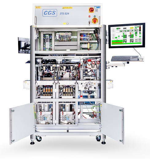
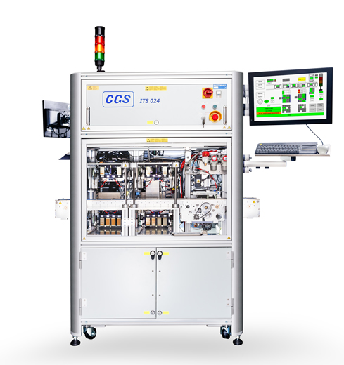
The CGS Inline-Test-Stations operate with the double stroke-probe-principle, which is covered by a European patent of CGS GmbH.
Main components
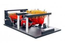
- Test-specific contacting elements (upper and lower cassettes) which are inserted into the insertion device of the test head
- Clamping device per cassette for fastening (pneumatic clamping set)
- 2-4 support cylinders depending on the type for lifting the device under test (DUT), as well as for pneumatic suspension
- Lifting cylinders for the operation of the cassettes to contact the DUT
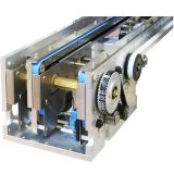
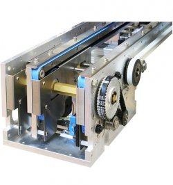
- one section of conveyor (inline module belt IMB)
The patented ITS-N5 to N7 probe systems are available with a VPC or Pylon interface and accommodate the corresponding DUT-specific upper and lower cassettes.
The ITS-N4 probe system is only available with a pylon interface.
Description
Usually the upper cassette carries the holding mechanism when contact is made on one side. The lower cassette carries the needle bed, the so-called application. When contact is made on both sides, the upper cassette can also contain sensors or pneumatic actuators, whose control signals are supplied via their own interface. The contacting of test points on the component side as well as the adaptation of small connector strips is possible from above. An activation and deactivation of test points (two-stage adaptation) can be integrated into the cassettes. The cassette change time is less than one minute. Both cassettes are pressed onto the interface with the pneumatic clamping devices. Thus, a connection is established from the external test system (e.g., CGS MFTS500) to the application. In the first step of the test cycles, the DUT is transported on the conveyor into the center of the test head, where it is held in position for contacting with conveyor stoppers.
Contacting
Supporting and lifting cylinders drive both cassettes in a continuous path sequence. The steps for contacting are:
- Raise the lower cassette by activating the support cylinders
- Simultaneous lifting of the DUT from the belt by extending the lifting cylinder. The centering pins (catch pins) automatically fix the DUT onto the lower cassette
- Lowering of the upper cassette by further extension of the lifting cylinder
- The hold-down mechanism of the upper cassette presses the DUT on the needle bed of the lower cassette
- The supporting cylinders act as pneumatic springs and keep the contacting unit (lifting cylinder, lower cassette and upper cassette) on level
- The electrical connection to the application is established
These steps characterize the patented double-stroke principle of all CGS test heads.
| N4 | Technical Data: PCB-Size: 100 x 110 mm Dimensions / Acessories: Dimensions im mm (W x D): 350 x 700 |
|---|---|
| N5 | Technical Data: PCB-Size: 160 x 200 mm Dimensions / Acessories: Dimensions im mm (W x D): 400 x 750 |
| N6 | Technical Data: PCB-Size: 450 x 250 mm Dimensions / Acessories: Dimensions im mm (W x D): 650 x 800 |
| N6L | Technical Data: PCB-Size: 450 x 450 mm Dimensions / Acessories: Dimensions im mm (W x D): 650 x 800 |
| N7 | Technical Data: PCB-Size: 320 x 320 mm Dimensions / Acessories: Dimensions im mm (W x D): 750 x 1100 |


